|
CNPS Petro Equipment Co., Ltd.
|


mud logging equipment named shale density meter
| Price: | 500.0 USD |
| Payment Terms: | T/T,L/C,D/A,D/P |
| Place of Origin: | Shandong, China (Mainland) |
|
|
|
| Add to My Favorites | |
| HiSupplier Escrow |
Product Detail
Application:
oil and gas mud logging
Resolution:
0.03 g/cm3
Measuring range:
1-3g/cm3The min
Warranty:
1 Year
he Instruction of
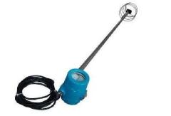
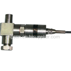
CNPS-ML-B11 Mud Density Sensor
CNPS Petro Equipment Co., Ltd.
The CNPS-ML-B11 drilling fluid density sensor is a single crystal silicon resonant density sensor for measuring the density of drilling fluid. The sensor adopts EJA118W, a diaphragm-sealed differential pressure transmitter imported from Japan, which has the advantages of high measurement accuracy, stable performance, and good repeatability. The outer mounting bracket is made of stainless steel, and it is corrosion-resistant and has a long service life. The base is detachably attached with a long rod, which can be adjusted according to the depth of the mud. It is an important sensor for oil and gas exploration work, which can be applied to various harsh environments such as oilfields.
1 Working Principle
The CNPS-ML-B11 drilling fluid density sensor uses a differential pressure differential mode of operation. Two pressure bellows with corrugated membranes installed at different heights detect the pressure difference produced by the liquid at different depths. The pressure difference is proportional to the liquid density. The two "H" shaped vibration beams on the sensor convert the differential pressure signal into a frequency signal, send it to the pulse counter, and then pass the difference between the two frequencies directly to the CPU (microprocessor) for data processing. After D/A conversion, Output 4 to 20mA standard DC current signal corresponding to drilling fluid density can also be directly transmitted by digital signal.
EJA118W transmitter can also transmit data through digital communication mode through I/O port and external device BT200. That is to use HART protocol (1.2kHz) to superimpose data signal on 4~20mA signal line. When data communication, frequency signal No interference effect on the 4-20mA signal.
2 Technical indicators
Power supply:+17V ~ 42V DC(Recommend +24V DC)
Measuring range:0.96 ~ 2.76g/cm3(Can be set according to user needs)
Output current:4~20mA DC
Measurement accuracy: ±0.5%FS
Environmental conditions:Sensor working temperature -40℃ ~ +85℃
Relative humidity:5 ~ 95%RH
3 Operation
3.1 Sensor installation
The distance between the two pressure diaphragm of the CNPS-ML-B11 drilling fluid density sensor is 1125px and 1500px, the outlet density sensor is 1125px, and the entrance density sensor is 1500px.
According to the needs of measurement, we choose to install sensors on the drilling fluid inlet and drilling fluid outlet respectively. When drilling fluid level fluctuates, the upper and lower flanges must be immersed in the mud to keep it upright and not tilted, otherwise it will affect the accuracy of measurement. The transmitter changer shall be above the mud level and not immersed in mud..
3.2 Sensor connection
Open the seal box cover sensor terminal,"+" SUPPLY +24V "-" power supply terminal connected to the signal shown in Figure 1.
|
|
|
Figure 1 Wiring diagram of density sensor
4 Sensor adjustment
The CNPS-ML-B11 type drilling fluid density sensor has been adjusted at the time of leaving the factory, and generally needs no on-site adjustment. If the sensor is in trouble, it must be adjusted on-site. The special calibrating instrument BT200 must be used. The adjustment method is as follows:
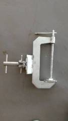
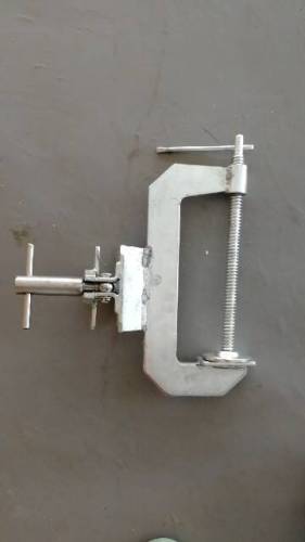
(1)Remove the protective cover of the lower end of the sensor, install the special pressure flange plate on the sensor diaphragm at the bottom of the sensor, and connect the outlet of the pressure detector and the pressure flange inlet to ensure that the seal is not leaking.
(2)Press the diagram to connect sensors, digital multimeter, DC power supply and calibrating instrument BT200 together, as shown in Figure 2.
Figure 2 Density sensor adjustment connection diagram
(3)The measuring range of CNPS-ML-B11 type density sensor is set to 0.96 to 2.76g/cm3 when the factory is released. When the sensor is placed in the air, the output current is 3.20mA..
According to the data given in Table 1, the output pressure of the pressure detector is adjusted and the output current value corresponding to the pressure difference is observed. If the output value deviates from the larger, the BT200 calibrator should be used to adjust the zero.
Table 1 Liquid density -- the corresponding relation between pressure difference and output current of two pressure diaphragm.
Two pressure diaphragm's spacing 1125px(Export density) | Density(g/cm3 ) | 0.96 | 1.32 | 1.68 | 2.04 | 2.40 | 2.76 |
Pressure difference(kPa) | 4.32 | 5.94 | 7.56 | 9.18 | 10.80 | 12.42 | |
Output current(mA) | 4.00 | 7.20 | 10.40 | 13.60 | 16.80 | 20.00 | |
Two pressure diaphragm's spacing is 1500px(Entrance density) | Density(g/cm3 ) | 0.96 | 1.32 | 1.68 | 2.04 | 2.40 | 2.76 |
Pressure difference(kPa) | 5.76 | 7.92 | 10.08 | 12.24 | 14.40 | 16.56 | |
Output current(mA) | 4.00 | 7.20 | 10.40 | 13.60 | 16.80 | 20.00 |
5 Sensor testing
If you want to use a simple way to test the sensor linearity, you can use the check flange, as shown in Figure 3. Remove the sensor shield and install the check flange on the sensor's lower end induction diaphragm. In the plastic hose in the water, first check the flanges of the deflation screw loosened, to add a certain amount of water to make the gas screw water overflow, and then screw tightened, gently tapping plastic hose, the tube wall of bubbles out. Then the power supply is attached and the ammeter is put into the output circuit to change the height of the liquid surface in the plastic hose. It can be seen that the output signal is changed. This change should be roughly in accordance with table 2.
Table 2 The relationship between the density of liquid and the height of water column and the output current.
Two pressure diaphragm's spacing 1125px(Export density) | Density(g/cm3) | 0.96 | 1.32 | 1.68 | 2.04 | 2.40 | 2.76 |
The height of water(mm) | 430 | 600 | 750 | 920 | 1080 | 1240 | |
Output current(mA) | 4.00 | 7.20 | 10.40 | 13.60 | 16.80 | 20.00 | |
Two pressure diaphragm's spacing is 1500px(Entrance density) | Density(g/cm3) | 0.96 | 1.32 | 1.68 | 2.04 | 2.40 | 2.76 |
The height of water(mm) | 580 | 790 | 1010 | 1220 | 1440 | 1650 | |
Output current(mA) | 4.00 | 7.20 | 10.40 | 13.60 | 16.80 | 20.00 |
Sensor test connection diagram
6 Maintenance
(1)The transmitter part must be sealed to prevent water damage..
(2)The sensor is designed to withstand shock and vibration, but it should be installed in places with less impact and less vibration.
(3)The two flanges of the sensor should be flushed regularly. If the cleaning is not in time, the sludge will be blocked and the flange will affect the measurement results. It is forbidden to clean mud with screwdrivers and other sharp appliances, so as not to damage the flange diaphragm, and affect the measurement results.
(4)When the sensor is not used, the residual liquid in the flanges of the flanges should be thoroughly cleaned.
Related Search
Find more related products in following catalogs on Hisupplier.com
Company Info
CNPS Petro Equipment Co., Ltd. [China (Mainland)]
Business Type:Manufacturer, Trading Company
City: Dongying
Province/State: Shandong
Country/Region: China (Mainland)